

How To Install Chain Spreader
How to Install Chain Link Fence, Steps and Photos
Useful tools for installing chain link fence: Tape Measure, Level, Pliers, Wire Cutters, Sledge Hammer, Post Hole Digger, Wheelbarrow, Shovel and Hoe to Mix and Transport Physical, Hacksaw or Pipage Cutter, Cord / Mason Line and Stakes, Crescent Wrench, Fence Stretcher.
| Description | Picture | Quantity to Use |
|---|---|---|
| Debate Material |  | Usually sold in rolls of 50 feet |
| Pinnacle Rail |  | Total footage of contend less gate openings |
| Line Posts (intermediate posts) |  | Divide total footage past ten and circular upwardly (meet chart below) |
| Last Posts (end, corner, and gate posts) (unremarkably larger than line posts) |  | As required (2 for each gate) |
| Top Rails Sleeve | 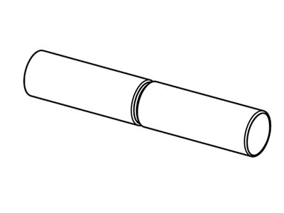 | 1 for each length of plain superlative rail. Not required for swedged tiptop rail |
| Loop Caps | 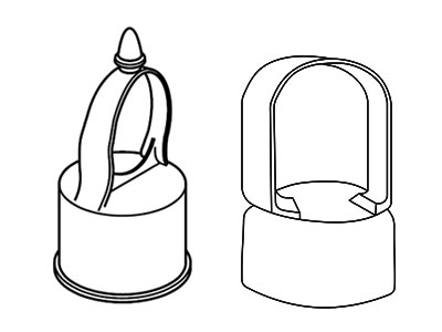 | Use 1 per line postal service (2 styles shown left) |
| Tension Bar | 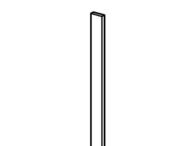 | Utilise ane for each end or gate post, 2 for each corner mail service |
| Brace Band | 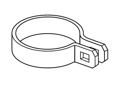 | Use 1 per tension bar (holds rail end in place) |
| Runway Ends |  | Use 1 per tension bar |
| Tension Ring | 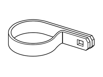 | Utilize 4 per tension bar or 1 per foot of fence peak |
| Carriage Bolts 5/16" x 1 ane/4" |  | Apply 1 per tension or caryatid band |
| Post Cap |  | Utilise 1 for each terminal mail service |
| Fence Tie / Hook Ties |  | one for every 12" of line posts and ane for every 24" of top rail |
| Walk Gate | 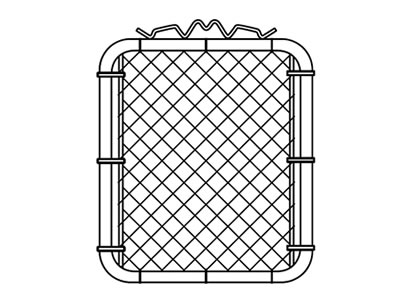 | |
| Double Drive Gate |  | |
| Male person Hinge / Post Hinge | 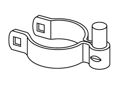 | 2 per single walk gates and 4 per double bulldoze gate |
| Wagon Bolts 3/8" 10 3" | 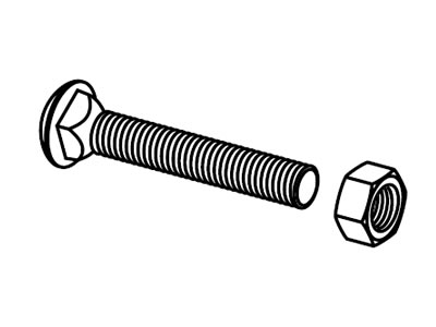 | i per male hinge |
| Female Hinge / Gate Swivel |  | ii per single walk gates and 4 per double drive gate |
| Carriage Bolt 3/8" ten 1 three/iv" |  | 1 per female swivel |
| Fork Latch |  | 1 per walk gate |
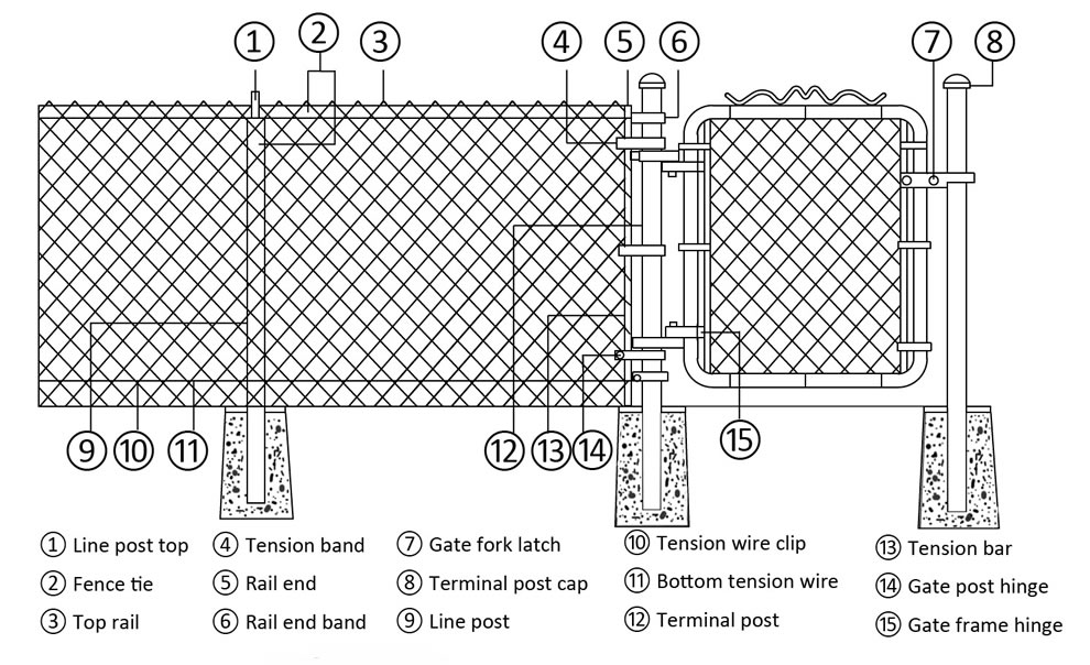
Needed accessories and located positions.
Preparing Fence Layout
Step one
Locate your property'due south boundary lines. Information technology is recommended that all posts exist set approximately 4" inside the property line and so that concrete footings practise not encroach onto whatever adjoining belongings.
Footstep ii
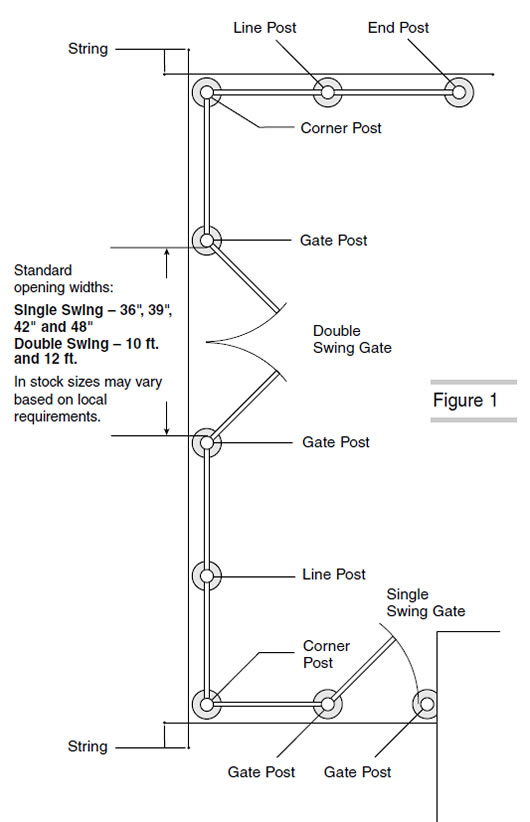
Measure out the overall length of your planned fence to determine how many anxiety of chain-link cloth and tiptop rail volition be required (Fig. i).
STEP 3
Marker the location of each terminal mail (corner, end, and gate posts are called terminal posts) with a pale. When determining the positions of gate posts, remember that clearance for hinges, latches, etc., is included in the listed opening width of the gate. Therefore, if you ordered a gate for a 36" opening, the post spacing should be exactly 36", inside post face to inside mail service face.
Setting Terminal Posts
Footstep one
Dig terminal mail holes approximately 8" in diameter and xxx" deep, with sloping sides (Fig. 2). The exact diameter and depth volition be determined past local weather condition and soil conditions.
Pace 2
With crayon or chalk, mark the ground line on posts. Height, in a higher place level footing, of terminal posts will equal the height of the contend material plus 2".
STEP 3
Center the terminal posts in the holes. Brand sure the posts are plumb and set at the correct peak. (Crayon mark should be at ground level.) Surround posts with concrete in a continuous pour. Trowel stop effectually posts and slope downwards to direct h2o away.

Locating and Setting Line Posts
STEP 1
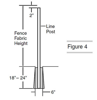
When the last post footings have hardened enough to stabilize the posts, stretch a string line taut between last posts. The string should exist positioned on the exterior face of the posts iv" below the top (Fig. 3). Top, in a higher place level ground, of line posts volition equal the acme of the fabric minus two".

STEP ii
Mensurate the distance betwixt last posts and refer to post spacing chart to determine the distance between line posts. Dig line mail service holes 6" wide and 18" to 24" deep, with sloping sides (Fig. 4). Heart the line posts in the holes. Make sure the posts are plumb, aligned with the centers of final posts, and set at the correct superlative. Surround posts with concrete in a continuous cascade. Trowel stop around posts and slope downward to direct h2o abroad.
Adding Fittings to Terminal Posts
STEP 1
After physical footings accept been allowed to sufficiently harden, skid the rail cease bands and tension bands onto the concluding posts. (Refer to parts list for the clarification and quantity of fittings that are required for various post types and heights.) The long flat surface of the tension band should face toward the outside of the contend (Fig 5).
NOTE: Have care not to spread or distort the fittings.

Pace 2
Apply all terminal postal service caps.
Terraced Footing Corner post associates is used at bespeak A to let fabric to follow terraced contour of basis (Fig. 6).
Very Uneven Ground Corner mail assembly is used at points A and B when ground rises or drops more 15" per 100 linear feet (Fig. 7).

Installing Height Rails
Stride 1
Place line mail superlative on the acme of each line postal service. The off-set round side should be toward the exterior of the fence (Fig. eight).

Step two
Insert one length of superlative rail through the line post peak closest to a terminal mail. Sideslip rail stop onto the terminate of the top runway and adhere it to a concluding post past using a track end ring. Secure by using a five/16" ten one-1/iv" carriage bolt with the head to the outside of the fence (Fig. 9).

STEP three
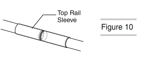
Effigy ten.Continue by forcing lengths of swedged finish top rail together through the line post tops. (If swedged finish top rail is non used, join lengths together with elevation rail sleeves.) (Fig. 10)
STEP four
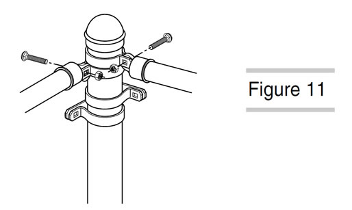
Upon reaching the next terminal postal service, measure advisedly and cut the height rails to fit tightly betwixt the last length of top rail and the rail finish.
Fasten runway cease to rails end band on the terminal post. Secure in place due west
itch a 5/16" x 1-ane/4" carriage bolt (Fig. 11).
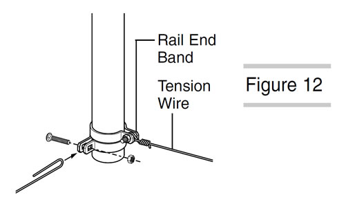
Installing Tension Wire (Optional)
Figure 12.Wrap tension wire once around bottom rail end band carriage commodities. Using pliers, twist several times to secure (Fig. 12). Tension wire should run along the same side of the posts equally the cloth. Apply tension wire clips no more than 24" apart, or equally needed for securing the wire to the chain-link fabric.
Hanging Debate Fabric
STEP i
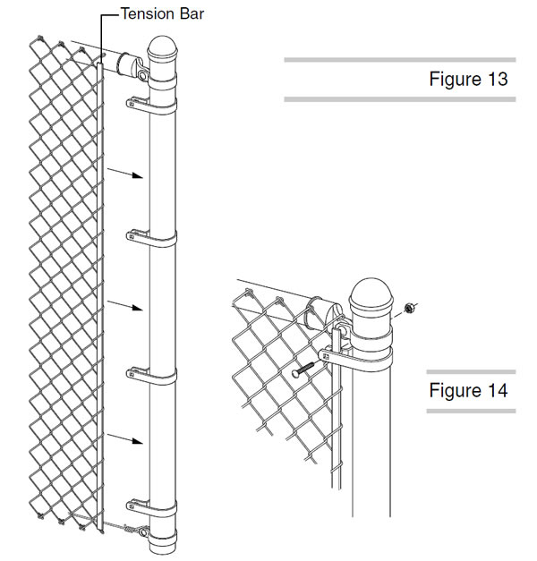
Starting at a terminal mail, unroll chain-link fabric on the ground along the outside of the argue line to the adjacent final postal service. Slide a tension bar through the first row of chain-link diamonds. Fasten evenly spaced tension bands (already on the post) to the tension bar, fabric combination using 5/16" x ane-1/4" carriage bolts with heads to the exterior of the fence (Figs. 13 & xiv).
STEP 2
Walk along the fabric and stand information technology up against the fence frame, taking out the slack equally you lot go. Loosely attach material to top track with a few debate ties to hold information technology in identify. Separate enough material from the roll to bridge the opening between the concluding posts.
To Remove Excess Fabric:
Remove the excess material with pliers by opening the meridian and bottom loops (knuckles) of a single strand of wire at the desired bespeak of separation. Unwind the strand up through the links until the cloth comes apart (Figs. xv & xvi).

To Splice Sections of Fabric:
Splice sections of chain-link fabric together using a unmarried strand of wire, removed from the end of the fabric. Join the two sections by winding the loose strand down, corkscrew style, through the finish links. Join and tighten the knuckles at pinnacle and bottom to secure.
Notation: Earlier sections can be spliced, a 2nd strand may have to be removed to provide a proper mesh.

Stretching Debate Fabric
Step 1
Temporarily insert a tension bar about 3 feet within the unattached cease of textile. Securely fasten one end of the fence stretcher to the tension bar and the other terminate to the terminal post (Fig. 17). Stretch the fabric. The correct fabric tension should allow a slight amount of give when squeezed by hand. Remove the temporary tension bar.
STEP 2
Adjust the fabric to verbal length by adding or removing wire as shown in figures 15 and xvi. Insert a tension bar at the end of the cloth and connect to tension bands on terminal post.

Hillside Stretch - Bias Cutting: (If Necessary)
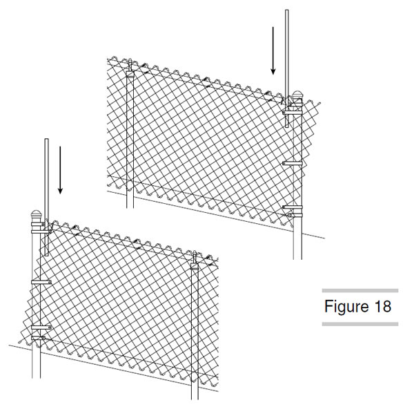
If the top of the chain-link fabric does non create a right angle to the final mail, the cloth must be cut on a bias and then that the tension bar tin slide into the material at the proper angle. Pull the chain-link material until the meridian or bottom, whichever is shortest, reaches the terminal post. The other corner of the fabric volition extend past the terminal post. Insert the tension bar at an angle through the material parallel to the last post (Fig. 18).
Remove the excess wire by cut the strands that form the diamond at the tension bar leaving them long enough to curve over the bar. Practise non cutting every wire. The number of wires cut depends on the caste of slope and the pinnacle of the debate.
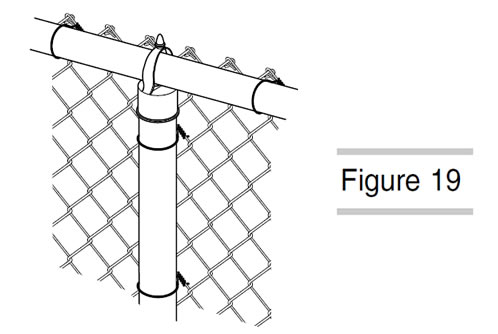
Installing Debate Ties
Fasten the fabric securely with debate ties spaced approximately 24" apart forth the meridian rail and 12" apart on each line post (Fig xix). Finally, securely tighten basics on all track finish bands and tension bands.
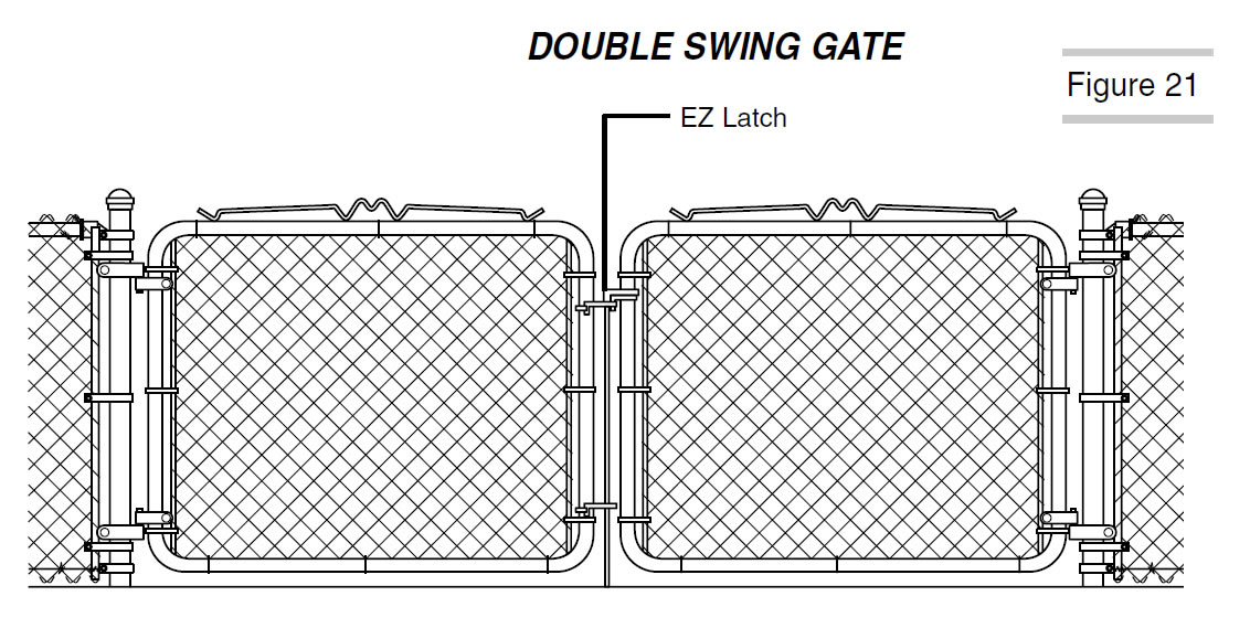
Hanging the Gate
A similar installation procedure is used on both single swing and double swing gates (Figs. 20 & 21).
STEP i
Apply gate postal service hinges to gate postal service approximately 8" from the top and lesser of the gate post with the top hinge pin pointing down and the bottom hinge pin pointing up. This volition forestall the gate from beingness removed and/or from dropping off. Tighten all bolts deeply.

STEP ii
Apply gate frame hinges to gate frame. Loosely fasten bolts and then they tin can be easily adjusted on the gate frame. Hang gate(s) in identify and then that the lesser of the gate has approximately ii" of ground clearance. Tighten the bolts on the lesser frame swivel get-go, then adjust and tighten the bolts securely at the top.
Step 3
Position gate fork latch at a convenient height. Tighten all bolts securely.
NOTE: Accommodate Latch Assembly on the double swing gate to the correct elevation and tighten all bolts securely (Fig. 21).

Source: https://www.chainlinkfencing.org/chainlinkfence/installchainlinkfence.html
Posted by: cadyfiresom1940.blogspot.com
0 Response to "How To Install Chain Spreader"
Post a Comment